
Why did we settle on the Kinect motion-sensing camera as our peripheral for Play the Knave? In the previous acts, we discussed some of the institutional and conceptual reasons for this choice: the hardware the ModLab had already modded for other projects and our interests in having players experience theater-making kinaesthetically. In this fourth act, we delve more deeply into the technical aspects of the Kinect as a motion-sensing device and discuss some of the ways we designed our Mekanimator system to address the Kinect’s particular affordances and constraints. That is, this act is about how we collaborated with the Kinect and the Software Development Kit (SDK) that Microsoft had released for it—a process that evolved through collaborations between our research team and end-users of Play the Knave, between the game and its players, and among players themselves.
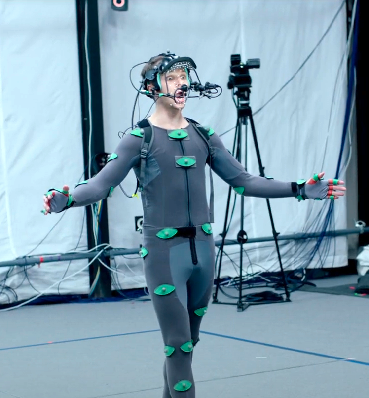
To understand our reasons for settling on the Kinect, it helps to know more about how different motion-tracking systems drive character animation—with the term character referring to the digital avatar on the screen, which also corresponds with the dramatic character from Shakespeare that our players enact when playing the game. There are two families of motion capture to consider. The first family (used in the Royal Shakespeare Company’s 2016–2017 Tempest production, for example, as discussed in Act V) is marker-based motion capture, wherein a performer dons a body suit dotted with infrared reflector markers arranged in a pattern designed for optimal measurements of joint movement. An arrangement of infrared cameras defines a capture volume, and software records and compares each camera’s view to triangulate marker positions in 3D space. Before motion capture can begin, the performer completes a calibration stage for the software that defines the range of motion and body dimensions. The result of the calibration is a skeleton model. After calibration for each performer concurrently in the space, motion capture can begin. This form of motion capture is renowned for producing high-fidelity data, but it is prohibitively expensive and time-consuming for casual play. Historically, marker-based motion capture was considered an offline method: the motion is captured, cleaned up (both automatically by algorithms and manually by technicians) in post-processing, and then applied to a 3D character model. Advancements in software have made it possible for marker-based motion-capture systems to compute the skeleton’s pose and apply it to a character in real time, exemplified by Shōgun from Vicon.[1] However, prepping the actor and running calibration steps are still mandatory.
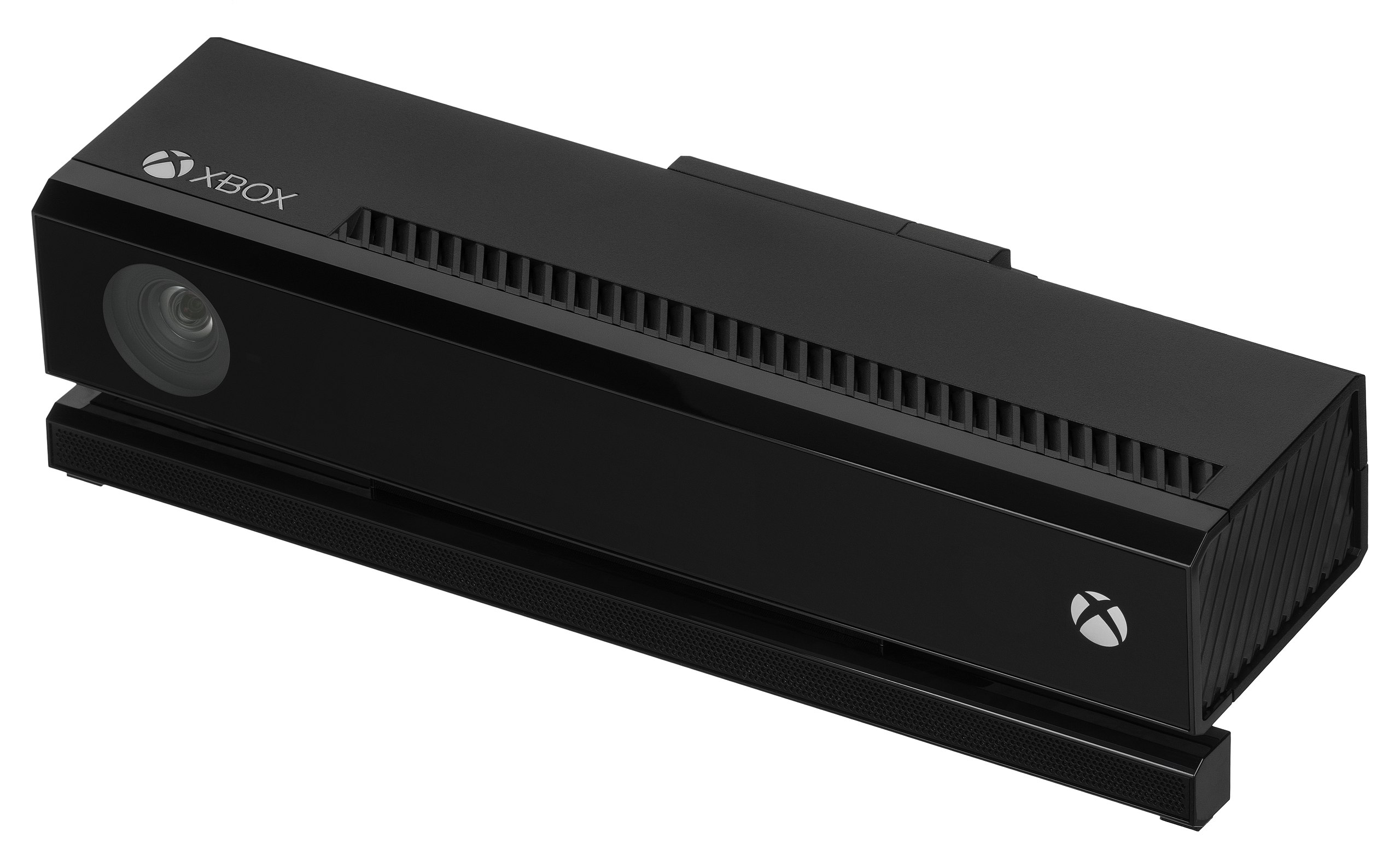
The second family, which we adopted for our project, is markerless motion capture. Some techniques for markerless capture use computer vision to detect features in color (RGB) data from a conventional webcam and reconstruct a body pose or face shape.[2] The technique employed by the Microsoft Kinect in the early 2010s works by analyzing images from a depth camera to derive skeletal data.[3] With images from a depth camera, each pixel stores a value representing distance from the camera. The original Microsoft Kinect (or Kinect v1) emits a structured infrared light pattern, which the depth camera reads. Because the emitted light has a known pattern, it is possible to estimate depth at each pixel by measuring the pattern distortion at each coordinate. The Kinect v1 captures a 640×480 resolution image 30 times per second, then processes the depth data with a skeletal solver that resolves positions and rotations for a skeleton composed of 20 joints. Rather than depend entirely on real-time computer vision techniques to find poses in the depth data, Microsoft used machine-learning techniques and trained a classifier to recognize a variety of poses from a large volume of depth data synthesized from a motion-capture database.
The Microsoft Kinect SDK released in February 2012 provides code libraries that allow developers to establish a connection to the Kinect and access data from its various sensors in the form of streams: color, depth, audio, and skeletal data can all be accessed from the device with relative ease. Consumer-level computers can power the Kinect v1 with a single USB 2 port. Considering the device’s price ($150 for the Xbox version, $250 for the Windows version), reasonable PC requirements, and software support, the Kinect v1 seemed an ideal fit for our needs.
Choosing the Kinect v1 created constraints for the rest of our development. The official Kinect drivers and SDK restricted our platforms to Windows and Xbox. Financially, it made sense to consider pursuing development for consoles; the cost of a capable PC and Kinect v1 sensor almost always exceeded the cost of an Xbox 360 and Kinect v1 bundle. However, the approval, release, and update processes for the console marketplace are considerably more difficult than for desktop PCs. In addition, choosing the Kinect v1 and its official SDK meant we were, at the time, choosing to exclude Mac and Linux operating systems.[4] For this and other reasons concerning modular design, networkability, and future devices—as we discussed in Act III—Mekanimator was developed as separate processes that coordinated via network connections and events. In turn, the Mekanimator process does not directly use the Kinect v1 SDK to read skeletal data. Rather, it receives skeletal data from a background process, or “daemon,” that establishes a connection to the sensor, processes and maps movement data for each player, and broadcasts the skeletal data for each frame to connected clients. Conceptually, this design yielded several benefits compared to directly accessing the device in-game. For one, we could now run the KinectDaemon on one device and the game on another. Because the game was being developed in Unity, we could now build and publish Mekanimator for Windows, Mac, and Linux—though playing the game would still require connecting to a PC equipped with Windows, the Kinect v1, and the daemon.
In theory, this architecture solved part of the multiplatform support problem and laid the foundation for connecting players online, a future though not-yet-realized goal for our software. In practice, both the daemon and the game were almost always running on a single Windows PC. However, this design choice made it easier to develop support for the Kinect for Xbox One/Kinect 2 for Windows (or Kinect v2) upon its release. The Kinect v2 is more demanding than the Kinect v1 in terms of power supply and GPU usage, requiring a dedicated power adapter in addition to a USB 3 port and a graphics card supporting DirectX11. In exchange, it offers a higher-resolution depth sensor that leverages time-of-flight rather than structured light, which yields greater body-tracking fidelity, a skeleton with more joints, and a limited range of hand and facial tracking. In other words, when using the Kinect v2, the avatars’ movements better reflect those of the player. But the cost of this performance is high. In developing support for the Kinect v2, we encountered several cases where a lab computer struggled to run both the game and the Kinect v2. Power issues occurred more frequently with the Kinect v2, especially with laptop computers. This made the option of running the game and KinectDaemon on separate physical devices even more appealing, but we primarily focused on addressing the issue with configuration changes: power and performance settings, driver updates (and freezes on updates to preserve system specifications), and physical USB port selection. The Kinect v2 had particularly bad power consumption issues on laptops despite efforts to run the relevant software with discrete graphics hardware, configure high-performance settings in Windows, and supply power to the devices using separate outlets in the room. Working with installations of Play the Knave in countries like South Africa (where power outages are more frequent) and in under-resourced schools in the U.S. (where power may be less robust due to older infrastructure) helped us consider another technique for laptop sessions: using a powered USB hub for connecting the Kinect v2 to the laptop. Despite the fact that the Kinect v2 uses its own power supply, the higher capacity in the USB hub works in favor of the device and cuts down on intermittent power losses.
“Joint by joint” | Skeletal Data
The Kinects and their respective SDKs provide solutions for key challenges of motion capture. From the player’s perspective, their avatar is mapped to their body movement soon after they begin moving in front of the sensor. Unaware of all that goes on behind the scenes to enable this mapping, players approach the system with the naiveté of Juliet, who, believing in the Petrarchan fantasy of love at first sight, tells her mother that she can be “moved” to “liking” Paris simply by “looking” at him: “I’ll look to like, if looking liking move” (1.3.101). Juliet puts this belief into practice the moment she sees not Paris but Romeo. In Play the Knave, when the player’s avatar appears on screen as if by magic and begins to mimic the player’s actions, it’s easy for players to follow Juliet in buying into a fantasy of immediacy. In fact, the player’s ability to move their avatar is no more straightforward and immediate than is the path from looking to liking in the romantic relationships most of us experience in the real world. Before the data the Kinect collects is ready for in-game use, a number of problems must be solved, and they fall into the following categories: mapping, coordinates, and retargeting.
Mapping
There are two mapping problems that must be addressed: the mapping of individual players to avatars, and the mapping of Kinect skeletons to 3D character models. We will address the player-to-avatar mapping first from the players’ perspective within Play the Knave. Then we will decompose the mapping process into sequences utilized by the components that make up Mekanimator.
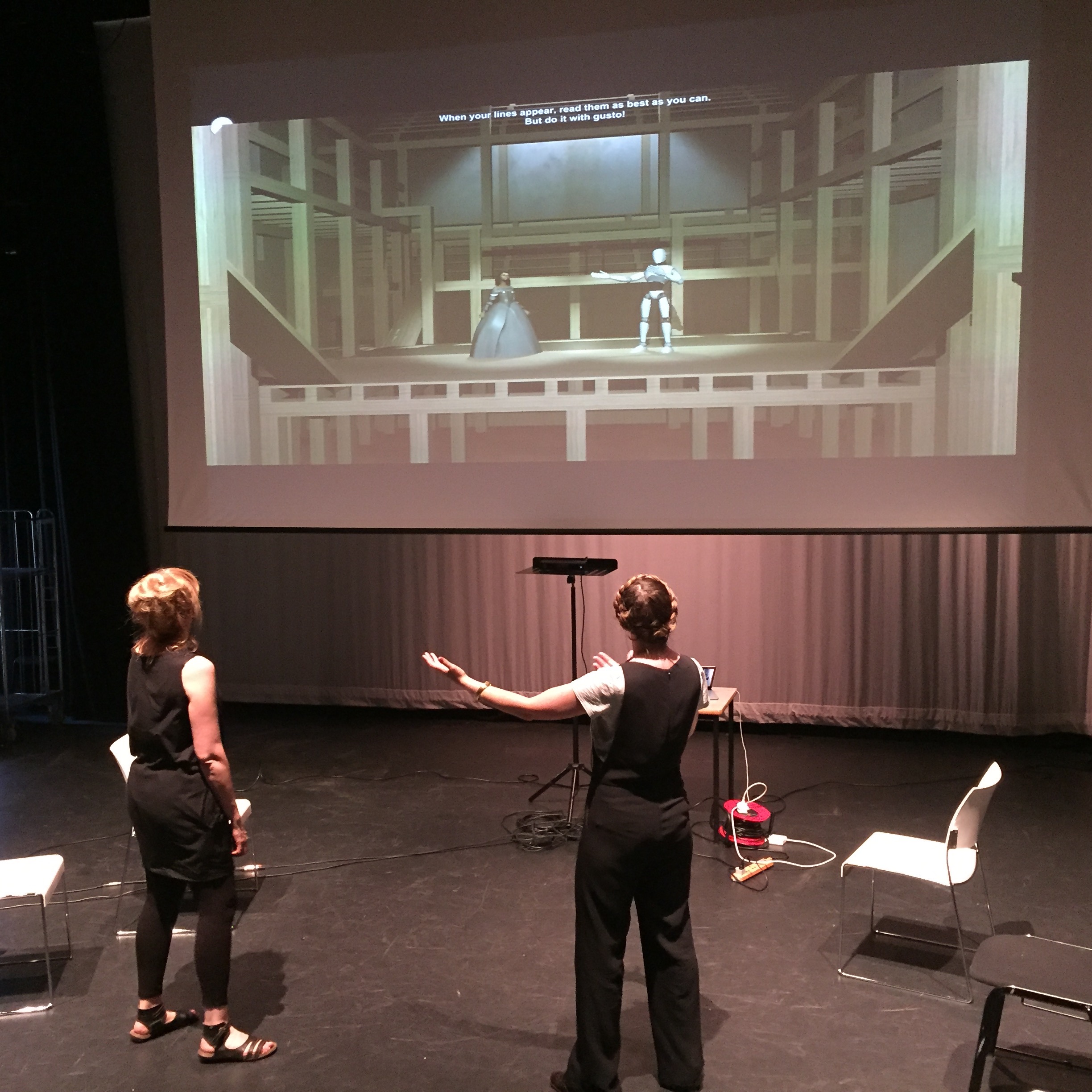
Because the Kinect begins tracking as soon as a body is visible in the play space, controlling the order of player-to-avatar mappings is important. It is necessary to specify the spatial conditions for this mapping to occur. Otherwise, if two players are in the play space together when a scene begins, there is no guarantee that a player will map to the avatar of their choice. We control this by specifying a sync line that appears in-game. In development, we found that this sync line is best set at 2 m distance from the Kinect sensor with a 30 cm tolerance margin. Prior to stepping on this sync line, players in the space can see their body movement in the game automatically mapped to a stick-figure avatar, indicating that they are visible but not yet mapped to a character avatar. At the beginning of a scene, an on-screen tutorial instructs players to stand in the back of the play space. Then the tutorial iterates over the scene’s characters and prompts a player to step onto the sync line, “the white line on screen,” so they may get mapped to that character’s avatar. Once all characters have been mapped to players, the sync line disappears, and players are free to move around the play space. If a player’s tracking is lost (typically due to leaving the space or occlusion from another player), their avatar disappears, and the sync line returns to help them repossess their character. Once a scene begins, avatar mapping is the first act of collaboration that players perform, and, for scenes of more than one player, perform together. Although cast assignments are not strictly enforced, it is possible for a player to accidentally or otherwise “steal” another’s avatar by approaching the sync line before their turn. Interesting problems and gameplay mechanics emerge out of this mapping system, which are best explained with a primer on the specifics of Kinect body tracking and a breakdown of the core components in the Mekanimator framework.
The Kinect reports skeletal data up to 30 times per second, limited by the capture rate of its depth sensor. Each of these captures produces a frame of depth data, analogous to the individual frames composing an animation. The Kinect hardware and SDKs solve for body poses on each of these frames using the techniques described prior on machine learning with depth images. In a frame, anywhere between 1 and 4 skeletons are present.[5] When the Kinect detects a new body, it is assigned a generated unique identifier to help track and differentiate it from existing bodies. A body ID stays consistent across frames while the player remains visible, but there are limits to this tracking. If a player leaves the capture (or play) space defined by the sensor’s visible range, the Kinect discards the body and its skeletal data. But if the same player returns to the play space, they are treated as a brand-new skeleton with a new ID. This can pose a problem for multiplayer games, especially with ours, where players may be given stage directions to exit and enter at different points in a scene.
At the SDK level, there is no support for detecting that a “new” player is the same person as one previously in the scene. While it is possible to attempt this at the application level with techniques such as comparing skeleton and bone sizes or using image data from the RGB sensor to identify facial features, it is not error-proof or necessarily practical. Thus, it is more prudent for the SDK to simply discard the previous body ID and associate a returning player with a new one. This scheme is simple, but it hands off the complications of persistence to the receiver of the Kinect data.
This is where the KinectDaemon comes in. The application level needs a mapping system to associate Kinect body IDs with characters. However, body IDs can change during a scene when players enter or leave, so a direct mapping is not feasible. The KinectDaemon resolves this in a flexible fashion. The Kinect body IDs are arbitrary values, and Mekanimator supports a range of scenes with up to 4 characters, so we need to manage these mappings with the use of up to 4 available skeleton slots skel:i, ranging from skel:0 to skel:3. The workflow is as follows:
- Kinect SDK identifies a body, and KinectDaemon maps the ID to the next unused skel:i slot.
- Mekanimator maps said skel:i to a stick-figure avatar to help the player move onto the sync line.
- When the body of skel:i remains on the sync line long enough to calibrate, KinectDaemon flags skel:i as ready for avatar mapping.
- Mekanimator unmaps skel:i from the stick-figure avatar and maps it to the next unmapped character in the scene.
For one-player scenes such as soliloquies, the mapping system is trivial: the first body available from the Kinect gets mapped to skel:0, and when calibrated, to the scene’s only cast member. However, having more players in a scene adds more moving parts, so to speak. Recall that Kinect body IDs are arbitrarily assigned, and because these are mapped to skel:i slots for calibration, it follows that skel:i slots are not necessarily in a dependable order. That is, skel:0 does not have to play the first character in a scene if skel:1 makes it to the sync line first. Therefore, the specific cast mappings are decided during play and are subject to change based on the players’ actions. The sync line mechanism provides a reliable ordering system for the mapping process. Assume this sequence of events occurs during a two-player scene with Player 1 choosing to play Romeo with the “Man in Purple” avatar and Player 2 choosing to play Mercutio with the “Noble Youth” avatar.
- Players 1 and 2 enter the play space and are given body IDs (for example) 0xBEEFBABE and 0xDEADBABE, respectively, by the Kinect SDK.
- In KinectDaemon, 0xBEEFBABE maps to skel:0 and 0xDEADBABE maps to skel:1.
- Both skel:0 and skel:1 are mapped to stick-figure avatars.
- Both skel:0 and skel:1 are mapped to stick-figure avatars.
- When the script calls for Romeo to step up to the sync line, Player 1 moves forward and skel:0 is remapped to the Man in Purple.
- When the script calls for Mercutio to step up, Player 2 does so and skel:1 is remapped to the Noble Youth.
These mappings persist for the duration of player visibility. But consider two possible scenarios:
Scenario A. The script tells Romeo to exit, so Player 1 leaves the play space; the script then tells the same player to return, and when the player does so, they are given body ID 0xDEADBEEF. When Player 1 leaves the scene, KinectDaemon registers the loss of 0xBEEFBABE and unmaps it from skel:0. Soon after, Man in Purple disappears from the screen. The next new body that the Kinect SDK sees gets mapped to skel:0 in KinectDaemon, assigned to a stick-figure avatar. When this body moves onto the sync line, Mekanimator reassigns skel:0 to the Man in Purple. As there is only one unmapped player, this is perfectly reasonable and Player 2 (Mercutio) remains mapped to the Noble Youth.
Scenario B. Both players leave the play space. Player 2 (Mercutio) re-enters the play space, followed by Player 1 (Romeo). Unlike Scenario A, this one is more ambiguous. Both players receive new body IDs, which get mapped to skel:0 and skel:1, in whichever order they are first seen. From the players’ perspective, their characters and costumes should remain consistent; if Player 2 returns to the sync line first, they might expect to be mapped to the Noble Youth again because of the previous mapping, and because they were the last player to leave the scene. But recall that KinectDaemon does not attempt any identification of previously seen bodies, to save on performance costs and to allow flexibility of stage directions during gameplay. To remap Player 2 (Mercutio) to the Noble Youth in this scenario, we could use a stack-based approach, where the next new body is mapped to the most recently unmapped character. However, if we use this approach and Player 1 stands on the sync line first, they would be mapped to the Noble Youth instead—-the player performing Romeo’s part would suddenly find themselves represented by the Noble Youth avatar. The issue is compounded in scenes with three or more players.
We found that a stack system works counterintuitively to the players’ experience acquiring avatars at the start of the scene. Thus, instead, we chose to assign the first body on the sync line to the avatar selected first, in this case the Man in Purple. This mapping system is consistent with the queue-based approach used at the start of the scene: the first body detected and synced by KinectDaemon goes to the first available cast member, determined by the order of the cast members’ definitions in the scene file. Then the next player on the sync line is mapped to the Noble Youth. This might feel counterintuitive to players at first, but it provides consistency with the initial mapping instructions. Note that with either a stack or queue-based system, scenarios in which only one player leaves and re-enters the space would get remapped without ambiguity as there is only one available character to control. With that in mind, the temporary loss of only one player’s body tracking at any given time is the most common tracking loss scenario, usually caused by them accidentally moving out of the play space or being momentarily occluded by another player. The advantages of queuing characters for unmapped bodies are only apparent with scenes that call for more players and the possibilities of them entering and exiting the scene.
Using a queue-based mapping system impacts how certain scenes are authored. Consider, for instance, the script “But One Cup” that Bloom and her colleague Lauren Bates created for teaching about alcohol-related violence through Othello, a scene that was written well after Play the Knave was released to the public and thus at a time when the software could not be significantly changed. There are four characters in this scene—Iago, Cassio, Roderigo, and Montano—but the scene begins with only Iago and Cassio in the action, as Iago pressures Cassio to drink. Once Iago has gotten him drunk, Iago calls on Roderigo to pick a fight with Cassio in hopes Cassio will lose his temper, as he does. A fight between the two ensues, and then Montano enters, attempting to break up the fight. For this scene to run properly, Roderigo must be listed third in the scene file and Montano listed fourth; if these are reversed, then the avatar selected for Montano will appear when Roderigo enters. Additionally, Iago and Cassio cannot leave the scene (they cannot exit and their avatars cannot get occluded) until both of the other characters have entered and received their avatars. Otherwise, the system would simply map the later players (Roderigo and Montano) to the first two characters (Iago and Cassio). The scene’s stage directions are carefully written to ensure that the queuing works, with the player for Montano being instructed to leave the play space entirely until it is their time to enter.
We can imagine a system wherein the stage directions indicate that a character leaves the scene permanently and Mekanimator recognizes that after this point in time during the scene, no new bodies should be mapped to said character. However, the problem becomes more tedious to solve if characters are instructed to leave and re-enter the scenes multiple times, as is the case in the “Fire-Eyed Fury” scene from Romeo and Juliet, where Tybalt leaves the stage after fatally wounding Mercutio, and then re-enters to fight with Romeo. When writing this and other scenes, authors had to consider carefully how KinectDaemon and Mekanimator manage body mappings, collaborating with the software. In the interest of keeping the system manageable, we chose not to pursue dynamic mapping changes driven by stage directions in Mekanimator. A facilitator running scenes with complex character changes still has the freedom to do so intentionally, with a prompt to inform the players of specific instructions and expectations. Overall, the player-to-avatar mapping system was meant to be straightforward and intuitive enough to support all the provided Shakespeare scenes, while leaving enough flexibility for more complex custom-written scenes and theater games such as “Object Impermanence,” which intentionally manipulates the mapping process.[6]
The next mapping issue deals with skeletal representations. In the Kinect for Windows SDK documentation, Microsoft has depicted the Kinect skeleton joints by modding Leonardo da Vinci’s sketch of the Vitruvian Man (c. 1490)—reinforcing how high-tech culture continuously invents itself by translating the past and suggesting that, as Hamlet might say, “The time is out of joint.” As we can see in these time-traveling diagrams (reproduced below), the Kinect v1’s skeleton contains 20 joints, while the Kinect v2’s contains 25, providing additional joints for the thumbs, neck, and spine.[7] Both provide a reasonable representation for tracking body movement—tracking limitations and pose ambiguities aside—even with lower bone counts than are typical of 3D character models. For instance, Unity’s HumanBodyBones model has labels for 55 bones, but 30 of these bones are phalanges in the hands, leaving 25 for the rest of the body.[8] If we ignore the issue of hand tracking for the Kinect, its skeletons are quite reasonably articulated for use with Unity characters. This allows for an effective 1:1 mapping between the Kinect v2 and Unity skeleton representations. We provide this by setting explicit labels for Kinect joints to associate them with values from the HumanBodyBones enumeration.
Coordinates
With Kinect joints being mapped accordingly to Unity bones, we are almost ready to begin applying the movement data to characters. As a prelude, we must handle the differences in coordinate systems between the Kinect and Unity and understand exactly how the movement data are represented.
With the Kinect v2, each tracked body contains a collection of joints. Each joint in a body has a position in camera space and an orientation in 3D. The Kinect provides this data for a tracked body, along with a tracking state for each joint based on the tracking quality. The possible tracking states include Tracked, Inferred, and NotTracked. This allows applications to programmatically decide for any given frame and joint whether the tracking is of sufficient quality to apply to the 3D character model. Joint positions use meters as units with respect to the Kinect’s location as the 3D origin—hence the descriptor of “camera space” for this data. A position consists of X, Y, and Z coordinates. The Kinect uses a right-handed coordinate system, which specifies how to interpret the positive and negative values for each dimension, by using the familiar right-hand rule in mathematics. Effectively, when looking at the Kinect head-on, +X is to the player’s right (the sensor’s left), +Y is above the sensor, and +Z is toward the player and away from the sensor. However, Unity uses a left-handed coordinate system. In effect, this means that the +X directions between the two systems are not in agreement. Without a conversion between the different coordinate systems, presenting the data as-is would result in the limbs appearing on the wrong side. Converting a right-handed position to a left-handed system is possible by reflecting the X dimension across the YZ plane: for each joint in the skeleton, joint.position.x = -joint.position.x.
Ordinarily, this would cause the player to perceive their movement as flipped: when the player lifts their right hand, the avatar’s right hand would lift as well, analogous to watching a video of oneself rather than looking at a reflection. However, the Natural User Interface guidelines for Kinect v2 specify that joints are produced from the SDK already in a mirrored fashion, so a sign flip is unnecessary.[9] Instead, we ensure that what the Kinect labels as right-sided joints are assigned to the avatar’s left-sided joints, and vice versa. Doing so effectively negates the need for an explicit coordinate sign flip and ensures that the player’s avatar appears to mirror their body movement.
Bone orientations are a little less straightforward, and they complicate the manner of interpreting motion-capture data and applying it to a 3D character. It is not sufficient to simply set the avatar’s skeleton’s joint positions to those of the Kinect’s. This is not typically how 3D character animation is driven. Skeletal models for 3D characters are often represented as a hierarchy; each joint in the skeleton is considered a geometric transformation, or transform, that contains a reference to a parent transform, a local position offset from its parent, and a local rotation offset from its parent. A root is a parentless transform that, unlike the other joints, can have its position and rotation explicitly set to change the general position of the character. The pelvis is commonly chosen as the skeleton root, as it is central and comparable to a human’s center of gravity. In practice, it is sufficient to set the avatar’s root transform position and rotation to that of the Kinect’s HIP_CENTER (for the v1) or SPINE_BASE (for the v2) joint. We can set these directly because the hierarchical nature of transforms dictates that a joint’s position and rotation in the world are computed relative to its parent’s world position and rotation. Computing the world transform of the right foot, for example, depends on finding the world transform of the right ankle, and then using the ankle to transform the right foot’s local position and rotation. But finding the right ankle’s world transform depends on finding the right knee’s transform, and that of the right knee depends on the right hip, which depends on the pelvis, which, as the root, terminates the hierarchical traversal. Since the avatar’s root transform has no parent, setting its transform values directly from the Kinect data results in the correct overall placement of the character, albeit without articulation for the rest of the body. One can imagine pantomiming with a toy doll held at the waist. For all other joints in the skeleton, however, we cannot explicitly set their positions or rotations to the values provided by the Kinect. For a joint with a parent, its local position is a vector that runs from its parent’s world position to the joint’s world position. The local position vector thus defines a bone, the length of which we expect to remain constant. The Kinect data provides world positions for each joint, and we know the parent-child relationship between joints by referring to their skeletal model, so it is possible to derive local positions for each joint:
joint.localPosition = joint.worldPosition – joint.parent.worldPosition.
Changing the avatar joints’ local positions directly is risky: doing so could cause the skeleton’s bone lengths to change, which is both unnatural for motion-capture movement and problematic for animating the character mesh. Moreover, changing the joint’s local position ignores updating the joint’s orientation, so the joint, and any of its children, would be oriented in the wrong direction even if its location were correct. To apply motion-capture data while preserving bone lengths, we can augment the local rotation of the joints instead of the local positions. Since a joint considers its parent as the origin in space, changing its local rotation will rotate the joint locally about the parent’s position while preserving its length, which yields more appropriate animation.
From this, we have a general strategy for handling coordinate differences between the Kinect and the avatars in Unity. First, apply the “SpineBase” Kinect joint’s position and rotation explicitly to the avatar’s “Hips” joint, and then apply local rotations to every joint in the avatar to which a Kinect joint maps. This first step, however, requires a little more information. The Kinect’s position values are given in meters, which are thankfully shared by Unity. However, the Kinect joints consider the physical sensor’s location as their spatial origin, which is not the case inside a scene in Unity. We need to decide where the Kinect is located virtually in the game itself so that a skeleton’s root position can be placed relative to it. When designing our software, we considered several different options:
- A. Manually set the sensor’s in-game location so it matches the physical location. This works fine for initial testing, but the skeletons will be placed incorrectly if you change the Kinect’s actual location. And every environment for the game may have a different physical configuration for the Kinect.
- B. Use the main camera in Mekanimator as the sensor location. With this approach, the game’s camera gives a truer view of how it sees the players, but this only works if your game camera and the Kinect sensor have roughly the same height and orientation. Again, this is not guaranteed or consistent.
- C. Choose a point in-game to be the origin and transform skeletal data relative to it. This approach helps divorce the game camera’s configuration from the physical sensor, but in turn, the game needs to perform extra work to decide where things will be placed.
Out of these, the third option turned out to be the most practical. Each stage in Mekanimator has an arbitrary transform added to it that represents the origin for incoming Kinect data. If avatars are placed relative to this origin, their on-screen placement should appear correctly. Before this can happen, however, we must account for the Kinect’s coordinate space. Recall that the Kinect’s Y dimension represents height above the sensor, so unless the sensor is placed directly on the ground, using the Kinect data as-is will result in players appearing partway into the stage’s floor. To account for this, we utilize the Kinect’s floor plane. On each frame that the Kinect reports a tracked body, it provides a FloorClipPlane property in the form of 4 floating point values (a, b, c, d). From geometry, the equation of a plane in 3D is:
ax2 +by2 + cz2 + d = 0
This defines the set of points (x, y, z) inside a plane defined by a normal vector <a, b, c> and a distance offset d. This equation is incredibly useful for converting Kinect coordinates into usable values for applications. The plane’s normal indicates the “up” direction for the floor from the perspective of the sensor. If the Kinect were perfectly level, then the floor plane’s normal would be <0, 1, 0>, and the distance d could be applied directly to each joint position’s Y component to find its true height. If the Kinect is not level, the distance d cannot be directly applied to the position data. First, we need to determine the angle between the floor plane’s normal and “true” up, denoted as <0, 1, 0> or the unit vector +Y. The dot product between the vector <a, b, c> and <0, 1, 0> gives us the cosine of the angle between these two vectors, and the cross product between these vectors gives us an axis of rotation around which we can rotate joint positions to correct the tilt offset. After rotating these positions, we can finally apply the distance d to the Y components of the rotated positions. Once this is done, the joint positions from the Kinect can be added to the stage origin in Mekanimator to give the correct positions of the skeleton in-game. This method handles transforming the Kinect position coordinates to in-game coordinates. If the characters are being displayed at a larger scale, we can also apply the scale difference to the position data before adding in the stage origin.
Guidelines from Microsoft highlight several factors that can impact the quality of the Kinect’s motion-capture data.[10] With the Kinect acting as both the infrared camera and light source, the sensor’s physical position and orientation are essential for producing good motion data. Elevating the Kinect and aiming it down provides better data for the floor plane estimation—but doing so introduces a tilt rotation that must be corrected before the skeletal data can be used. In our tests with play space configuration, we learned that the extra work to elevate the sensor, aim it at a downward angle, and transform its data to compensate for its orientation was all worthwhile. In this configuration, the depth image from the sensor clearly shows a large region of the floor, making it less sensitive to noise and yielding a more confident floor plane estimation (see image below, left). In contrast, keeping the Kinect at the ground level and aiming it straight out, or slightly up, results in poor visibility near the bottom of the depth image. Such a configuration causes less emitted infrared light to bounce off the floor and reflect towards the sensor (see image below, right). In turn, the floor plane seen in the depth data contains more variance, manifesting in the depth image as static, which creates frame-by-frame jumps in the tracking data, or jitter. The jitter in this configuration impacts both the floor plane estimation, which degrades the rotation transformation made to correct the sensor’s tilt angle, as well as the tracking confidence in the Kinect’s leg joints. This comes as no surprise to the graphics programmers, as it is behavior consistent with the use of Lambertian reflection for diffuse shading.
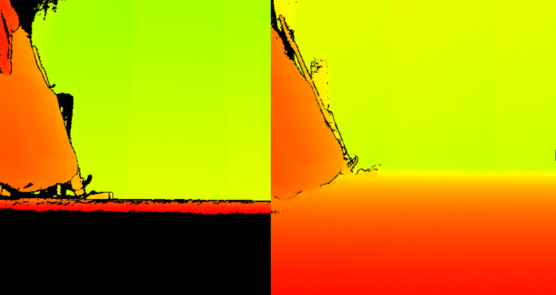
In Lambertian shading, we wish to apply color variations across an object by considering the object’s surface and the locations of the object, a light source, and a camera. We calculate how rays from the light source reflect off the object using the object’s surface normal at the bounce location. Measuring the angle between the reflected light ray and the ray defined between the camera and the object tells us how much light the camera receives from that point on the object’s surface. When the angle between the rays is 90° or higher, that point on the object’s surface is considered to be in a shadow since no light is reflecting toward the camera. When the angle is 0 degrees, the object’s surface is reflecting light directly into the camera and the area is treated as very bright. Any angle between these two extremes reflects a proportionate amount of light, which lets us shade the surface accordingly and helps us perceive the object’s surface definition. The same principle applies to the Kinect’s play space tracking quality with the floor plane. When the sensor is configured without any elevation or tilt, it receives the maximum amount of infrared light reflected off players, so joint positions are computed with high confidence. However, the floor plane reflects almost no light and it becomes more difficult to account for the sensor’s angle and position.
With good sensor placement, we can convert the position coordinates from the sensor’s camera space into a generic world space for any application. We expend considerable effort converting position data given that only the Kinect skeleton’s root position can be used directly on the avatar’s root joint. Recall that the non-root joint positions should be set by changing their local rotations, not their positions, so to complete the rest of the animation process, we need to apply various retargeting techniques.
Retargeting
In character animation, retargeting refers to the act of applying the same skeletal animation from one character to another. If the two characters have identical skeletons, this is straightforward. The destination character copies all the joint data from the source character, except for its skeleton root so that the destination character maintains its distinct position and rotation. However, it becomes a considerable challenge when there are differences between the two characters’ skeletons, such as:
- having different joints,
- having the same joints, but at different bone lengths or orientations,
- having the same joints, but with different enough meshes that the resulting animation has problems.
The Kinect skeletons have the same topology for each player, but each player’s skeleton may have different bone lengths. That alone warrants a need to account for differences in player proportions when assigning avatars. Thus, when each player stands on the sync line, KinectDaemon measures and records the length of the femur for the player. It is important that these length measurements all happen while the player is on the sync line. In addition to controlling exactly when a player is mapped to an avatar, restricting this measurement to occurring only on the sync line gives better consistency between players. Being the longest bone, the femur is, in most cases, a decent representation of the players’ scales. After 40 frames of measurements have been collected, which takes a little over one second at 30 frames per second, the femur lengths are averaged and saved. The body is then marked as ready for avatar assignment, at which point Mekanimator swaps the player’s stick-figure avatar for the avatar of the next available character in the scene. When the mapping is made, we define the avatar’s bone scale as the ratio of the avatar model’s femur length to the Kinect skeleton’s femur length. This bone scale can be applied to each bone in the avatar to effectively resize it with respect to the player. Proportionally, the bone scale is surprisingly dependable, although the resulting character height may not be a perfect match. An alternative to this is to compute a height scale as a ratio between the avatar skeleton’s height and the Kinect skeleton’s height. In testing, we found that this resulted in avatar sizes being slightly smaller than expected, and with limb proportions that did not fit as nicely to the player’s as when using the femur-derived bone scale.
Up to now, we have handled avatar positions and sizes relatively well by applying the root transform directly and using the bone scale to account for player–avatar size differences. To animate the rest of the character, we need to define rotations on each avatar joint, utilizing the rotation data as well as the position data of the Kinect joints. However, we must address that the skeletons of avatars can differ considerably. Recall that the Kinect uses a right-handed coordinate system, which dictates how to interpret positive and negative directions for the X, Y, and Z dimensions in 3D space. This same concept is at play when an artist creates a skeleton for a character model. While each joint in a skeleton may utilize the same coordinate system (as right- or left-handedness is typically universally set in 3D model applications such as Blender or Maya, used by many artists to create avatars), because each joint is defined relative to its parent, it is common to see changes in rotation when traversing the skeleton from a parent joint to a child. These changes in rotation are often intentional—one convention uses the joint’s local Y direction as the axis of rotation at the elbow or knee, as doing so helps constrain the joint’s range of motion and may be used to inform other animation techniques, such as forward and inverse kinematics, on which direction rotations should occur. When posing a character’s arm, depending on the skeleton’s configuration, it may be necessary for the artist to rotate the shoulder about the Z axis, then rotate the elbow about the Y axis. It is also common practice to define only one side of the body’s joints, such as the left limbs, and then use software tools to mirror these joints onto the other side of the body. This mirroring process may cause the rotation direction to change on the other side, resulting in a need for a rotation about -Z on the right side rather than +Z on the left side to achieve equal and opposite poses in both arms.
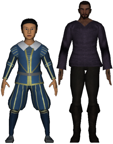
Convention, standard practice, and tools may assist technical artists in using a consistent system across the joints in the skeleton for an avatar, but there is no strong enforcement for conventions, and one encounters a wide range of skeletal configurations when importing models from online stores and asset packs or commissioning the creation of character models. Since the avatars in Play the Knave are sourced from all of these, we must expect that each of the 38 characters in Mekanimator may have a completely different interpretation of axes and directions throughout their skeletons. This significantly complicates the issue of retargeting from the Kinect skeleton to an avatar skeleton, as the transformations that work for one skeleton may not translate to another.
Early tests for applying Kinect rotation data to avatars involved applying hard-coded transformations to a joint’s rotation before applying it to its appropriate avatar joint. The idea was to better understand rotation data from the Kinect and to see if a simple transformation would be possible for all cases. Such transformations might include applying 180° rotation about +Y, either before or after assigning the Kinect’s rotation to the avatar joint. It is easy to imagine how many variations and combinations are possible with such forms of transformations. To help us iterate these options faster and provide immediate visual feedback, we developed a tool component for Unity Editor that let us choose a specific joint and manually specify the order of individual X, Y, and Z axis rotation operations to apply to the joint from the Kinect data, along with optional pre- and post-rotation adjustments for each axis. Following the creation of this tool was a long series of trial-and-error tuning sessions to understand how to apply each Kinect joint’s rotations to the appropriate joint on a single avatar. The result of a tuning session is a collection of rotational reorders and adjustments that, when applied to an avatar’s joints in a designated order, would produce an acceptable character animation in Unity from the Kinect’s rotation data. While developing with the Kinect v1, we went through the process of defining these retargeting definitions for each of the avatars. If a set of avatars came from the same asset pack—as is true for most of the avatars categorized as “Modern” in the game (see video below)—and shared a common skeleton, we could effectively reuse the retargeting file from one avatar for the rest in the set. However, every time we added a new avatar to the game, we had to repeat this process.
To help streamline the process, we utilized the tools from the Kinect SDKs. Kinect Studio, available in both v1 and v2 SDKs, allows one to record data from a Kinect, including the color and depth stream and the resulting body movement data. Like traditional marker-based motion capture, we recorded a range of motion (ROM) session where an actor would demonstrate the bends and rotations of each major joint, one at a time. Then we would replay this data on a loop for KinectDaemon, which processed it just as if it came from a sensor. In the Unity Editor, we could toggle the manual changes to rotation for different joints in an avatar skeleton until we found a configuration that worked for that character. Fortunately, the central joints, such as the pelvis, spine, and shoulder center, did not usually require any retargeting—the most common case was a 180° rotation about +Y on the avatar root to make the character face the camera. Retargeting most often dealt with the limbs, neck, and head.
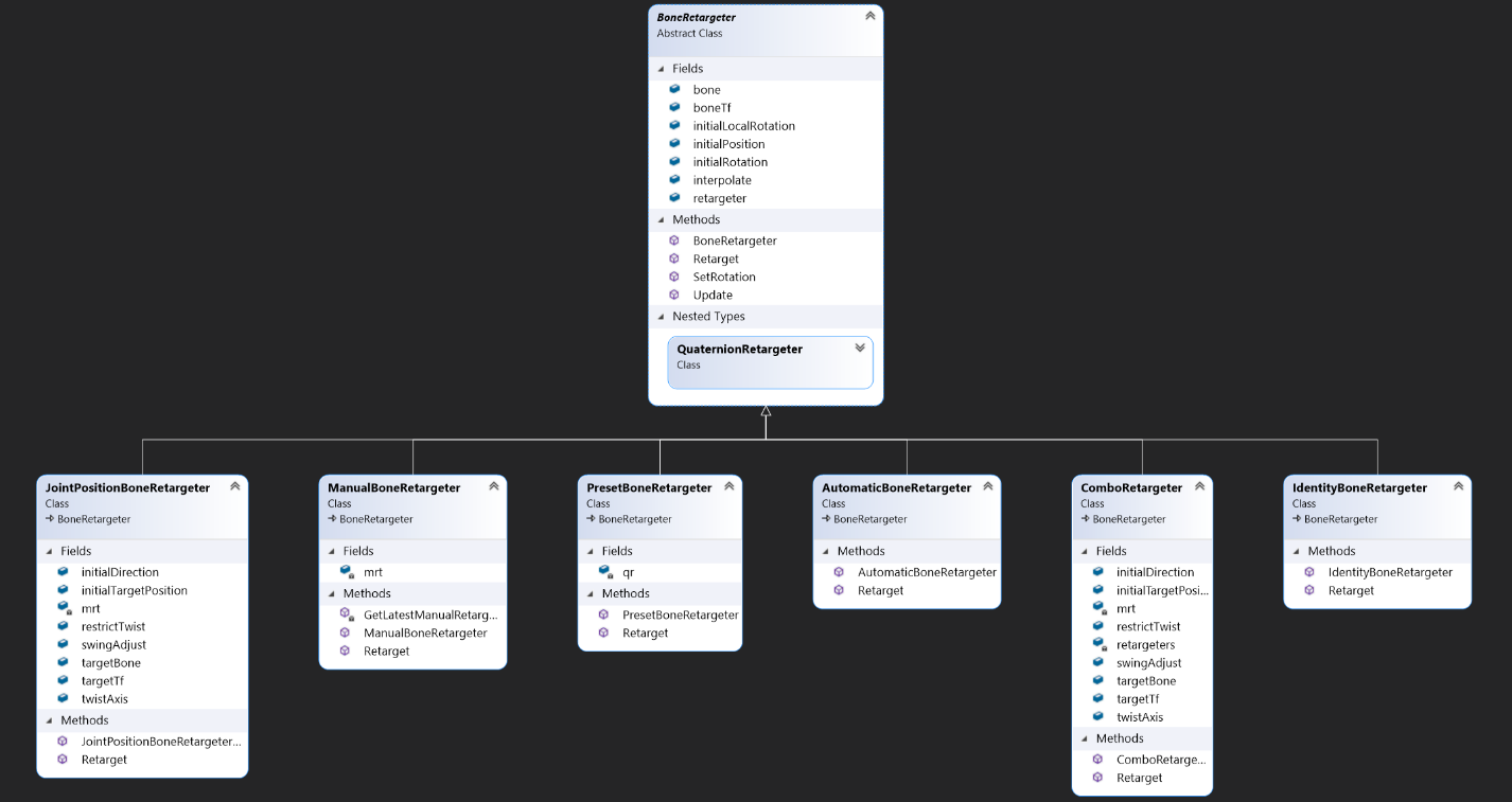
Manually retargeting the rotation data from the Kinect helped us establish character animation driven by the players. However, it was tedious to define manually and subject to error in certain situations. For instance, although the Kinect data required some transformation, we found that no simple set of rotation adjustments would produce consistently correct head and neck movement. This led us to define variations of the retargeting system, where each specialized case could apply a more involved technique. This deviates from the original retargeting attempts, which assumed that the process could be completed independently for each joint. Instead, it was sometimes necessary to account for other joints in the skeleton (usually the parent and/or children of a joint). The class diagram shown here represents the variations of the retargeting options. In code, a Character object maintains a collection of BoneRetargeter objects, up to one for each Kinect joint. BoneRetargeter is a base class that specifies common properties, such as the Kinect joint and associated avatar joint, the initial avatar joint’s transform data, and the default length of the avatar’s bone. It also defines a virtual method called Retarget that its derived classes can override. In the base class, BoneRetargeter.Retarget(frame) will accept the current frame of movement data for a body from the Kinect as input, transmitted via SSCP from KinectDaemon, and return the input world rotation as output for the Kinect joint associated with the retargeter . In short, the base class makes no effort to retarget the movement data, and simply returns what it sees. Instead, the actual effort to compute appropriate rotations for the avatar joint based on the Kinect data is left to the derived classes, as each one can follow a different scheme. For instance, the QuaternionRetargeter effectively performs the same manual retargeting work that we defined in Unity Editor interactively, applying a predefined manual reordering of the rotation’s axes and optional pre- and post-rotations to the Kinect joint’s rotation data before applying it to the avatar joint.
From the perspective of the Character object, the choice of BoneRetargeter-derived instances for each joint is agnostic. The Character simply maintains a collection of BoneRetargeter objects, leveraging polymorphism, and calls the appropriate overloaded Retarget method for whichever derived class is instantiated. To determine which BoneRetargeter derived class to instantiate for each joint, we provide a predefined schema for each avatar in the game. An example of this kind of schema is given below:
{
    "Hips": {
        "auto" : true
    },
    "Neck": {
        "target" : "Head",
        "twist_axis" : [0.0, 1.0, 0.0],
        "swing_adjust" : [0.0, 180.0, 0.0]
    },
    "LeftUpperLeg,LeftLowerLeg": {
        "pre_adjust": [180.0, 90.0, 0.0]
    },
    "RightUpperLeg,RightLowerLeg": {
        "pre_adjust": [180.0, -90.0, 0.0]
    },
    "LeftUpperArm": {
        "target" : "LeftLowerArm"
    },
    "LeftLowerArm": {
        "combo" : true,
        "pre_adjust": [0.0, 180.0, 0.0],
        "target" : "LeftHand"
    },
    "RightUpperArm": {
        "target" : "RightLowerArm"
    },
    "RightLowerArm": {
        "combo" : true,
        "pre_adjust": [0.0, 180.0, 0.0],
        "target" : "RightHand"
    }
}
In this instance, “auto” for the “Hips” joint specifies that the Character should load an AutomaticRetarger instance which will simply apply the world rotation from the Kinect data to the initial rotation of the joint in the avatar. Other retargeting definitions are more involved. The neck joint’s retargeter, for example, specifies the head as its target bone. The rotation data for the neck joint that comes from the Kinect sensor is not readily usable on the avatar. It lacks the expected range of motion and does not correctly pose the character’s head when applied directly. Instead, this retargeter will attempt to find the appropriate angle of rotation for the neck by comparing the angle between two vectors: one defined by the difference between the world positions of the neck and the head from the Kinect data, and another defined by the same difference but from the avatar. When the angle is known, the axis of rotation can also be computed. Together, knowing the axis of rotation and the angle of rotation between these vectors allows us to define a rotation transform for the neck to pose it accordingly. To get an accurate final pose, this retargeter takes the initial step of first resetting the avatar’s neck joint’s rotation to its initial value. Without this step, the computed rotations to apply would accumulate on every frame. This retargeter also defines a twist axis—with the neck, we aim to capture twists around the Y axis as well as swings around the X and Z axes. Doing so allows us to decompose the computed rotation into separate values for swing and twist. Without this step, the avatar’s neck has little ability to look left or right.
Other joints require similar levels of additional work to retarget. For example, the left lower arm (or left elbow) utilizes a ComboRetargeter which first adds a rotation of 180° around the Y axis to the rotation data from the Kinect. After doing so it applies a JointPositionBoneRetargeter , as used for the neck, with the target bone set to the left hand. In this sense, the retargeting process is designed to be extremely modular with various combinations and techniques available depending on the joint. Regardless of which BoneRetargeter is used, each one is expected to provide a rotation value that can be applied to a joint in the avatar. From experimentation, we understand that the Kinect’s joint rotation values are given as world coordinates, without regard for the joint’s parent. We can convert these into local rotations by multiplying a joint’s world rotation by the inverse world rotation of its parent, but in practice this is not necessary if we design the BoneRetargeter instances to set the world rotation at the avatar joints instead of the local rotation. One could safely assume that doing so without regard to order would introduce even more problems, but such problems can be avoided for two reasons. First, Unity’s Transform objects are designed to represent transforms with a hierarchy structure, so they are responsive and self-maintaining. If Transform p is the parent of Transformt, changing the position of t will both update the world position for t and the local position for t with respect to p. The same behavior applies when setting t’s rotation to a world rotation value. Next, because retargeting schemes can vary for each joint in a skeleton, and because each avatar joint’s Transform will auto-update when its world values are changed, we must apply the retargeters using the skeleton’s hierarchy, starting at the avatar root and moving down through each of its children into the rest of the body such that a parent is always retargeted before any of its children. If we do not follow this update order, it is possible to create scenarios where the placement of a retargeted joint needs to be overwritten after retargeting that joint’s parent. Note that in the example given, only 10 joints have retargeting profiles defined, leaving 15 joints without retargeter definitions. When a joint does not have a retargeter definition, it is safe to assume that the connected data can be directly applied to the avatar.
Whichever BoneRetargeter is in use, they each adhere to an update principle based on their joint’s TrackingState value as reported by the Kinect v2 SDK.[11] If the tracking state is reported as Tracked, the computed rotation can be applied to the avatar joint. If the TrackingState is Inferred, then the avatar joint is assigned a 50/50 blend between its current rotation and the rotation computed by the retargeter, reflecting that the confidence rating for the joint is lower and should not be trusted. When the TrackingState is NotTracked, we can elect not to update the avatar joint’s rotation at all. Considering that these states change up to 30 times a second, the use of different strategies based on a joint’s TrackingState helps prevent larger animation glitches while also allowing the avatar to “catch up” when tracking quality improves.
“Smooth success” | Connecting with Kinect
As discussed in the previous act, Mekanimator’s data flow operations are typically handled using the source and sink paradigm. KinectDaemon is responsible for starting a server and acting as a source for each tracked body, to which Mekanimator connects as a client and registers itself as sinks for various stream names. KinectDaemon registers each skel:i slot as the name of a data source that provides messages of type “skel,” which are constructed programmatically from the mapped Kinect body assigned to skel:i. A message of this type represents a single frame of movement data for a Kinect body and includes the following:
- the world and local positions and rotations of each joint in the body,
- the floor plane perceived by the sensor,
- the skel:i slot assigned to the body,
- whether the mapping process has been completed on the sync line for the body,
- the femur length,
- the current timestamp and frame number.
By default, Mekanimator maps all skel:i sources to their own stick-figure avatars and only displays them when the source from KinectDaemon reports a body as tracked but not yet ready for avatar mapping. If KinectDaemon does not send any messages for a particular skel:i channel, Mekanimator assumes the body is not tracked and hides the avatar for that channel until a body is identified. To help display the correct number of avatars for untracked players, on each “skel” message, KinectDaemon reports the difference between the number of bodies seen and the number of skeletons mapped on the sync line. When this number changes from one frame to another, Mekanimator updates how many stick-figure avatars are visible and to which players they are mapped. If KinectDaemon reports 3 bodies but only 2 of them are mapped, Mekanimator can ensure that only 1 stick-figure avatar is in use for the unmapped player. Then, when the last player is mapped, Mekanimator will hide the last stick-figure avatar and assign a character avatar instead.
This scheme works to the player’s advantage as they begin a scene. The stick-figure avatar allows the player to accurately approach the sync line, and doing so automatically swaps them into a character’s avatar to inhabit for the scene. In group situations, players are quick to identify their specific stick-figure avatar by tuning into the visual feedback loop between their own body movement and the presented view of their movement data. In the same fashion, if KinectDaemon loses track of a player, their avatar disappears completely and is not replaced by a stick-figure avatar until the sensor can see their body again. As KinectDaemon runs, it compares the known list of body IDs to those currently mapped to skel:i slots. Any bodies currently mapped to a skel:i slot whose IDs are not present in KinectDaemon’s list of tracked bodies are unmapped from their skel:i slot and removed from the list. Because these bodies are unmapped, no subsequent messages are sent for the associated skel:i slots. Thus, Mekanimator needs a way to evaluate when a skel:i source is no longer serving new data. This is one issue that arises when working with sources and sinks. When should the sink determine that the source has been shut off? How does it differentiate between a momentary interruption of data and a disconnection? We could try to send a disconnect message from KinectDaemon. However, the interpretation of this is not immediately evident from the perspective of Mekanimator. After all, when KinectDaemon sees a new body, it will assign it to the next available skel:i slot, so we do not want to disconnect the source from the sink explicitly because it may be used again quite soon. As an alternative, on the Mekanimator side we track the elapsed time in between “skel” messages. If more than half a second passes between receiving “skel” frames from a source, we assume that the tracking for that body has been lost. This threshold was chosen with trial and error and amounts to about 15 consecutive frames without data from the Kinect. When this happens, Mekanimator sets the visibility of that character’s avatar to be hidden. Any updates to the character pause until a new body has been mapped to the character using the sync line mechanic in KinectDaemon. When tracking is lost for a skel:i slot, Mekanimator will reassign that slot to a stick-figure avatar and keep it hidden until KinectDaemon reports a new body that has not completed the sync line step.
There is another scenario in which we wish to disable the tracking for a character’s avatar. Certain playing conditions can affect the tracking quality of the skeleton data such that attempting to apply them to an avatar will produce disastrous results. This might include rapid position changes in joints, strobing or popping behaviors on limbs, sinking or hovering depending on the floor plane tracking quality, and more. The cause of such play conditions could include playing in direct sunlight, which has a massive amount of infrared light that interferes with the Kinect’s abilities to measure depth and produce quality skeletal data. Sometimes, playing in a dark environment can have adverse effects on the tracking quality as well. Rather than subject the players to an ongoing display of glitches and pops that are otherwise tolerable in an intermittent fashion, we check to see if more than half of the skeleton joints in a body are labeled as NotTracked by the Kinect SDK. When this happens, we treat the entire character as untracked and disable the avatar’s visibility. This gives leeway to situations where a considerable number of joints are temporarily occluded, such as when a player walks in front of another or moves partway out of the play space but does not completely leave. In these circumstances, the majority of the Kinect joints are still at least Inferred, and we can minimize visibility changes for the character.
Even with good conditions for play—ample lighting without direct sunlight, plenty of room for the number of players in a scene, good placement of the Kinect with a clear view of the floor and some elevation above it, and sufficient power to run the devices—the body-movement data reported by the Kinect SDK are derived from depth data measured with infrared emitters and sensors. Although the Kinect v2 provides considerably higher tracking quality than the Kinect v1, both are subject to infrared noise and discontinuities in movement data. This means we need to apply smoothing and filtering to the observed movement data before applying it to a character. To compartmentalize the responsibilities of the components in the Mekanimator framework, we decided that KinectDaemon would only serve as a source for movement data as reported by the SDK without applying any sort of smoothing or filtering passes. If KinectDaemon is configured to save body movement data to a file, the data is saved without any modifications. This design preserves the original movement data and allows it to be replayed with any choice of smoothing or filtering technique applied by the receiver. Thus, Mekanimator handles the operations of filtering movement data before applying it to characters. Any filtering operations occur in Mekanimator after a sink receives the movement data for a body, but before it is applied to a mapped character.
When deciding on an appropriate filter technique for the Kinect’s movement data, we keep in mind the fact that the players are performing dramatic scenes. To encourage as much creativity as possible, we want to support a wide range of expressive movement without overly instructing our players to avoid certain actions. Prior to discussing the filters further, it is important to acknowledge how the Kinect’s design influences performances. For instance, players are tracked better when they face the sensor rather than each other, resulting in a style of acting that requires the characters to address the audience more than each other. If players turn to face one another, the Kinect struggles to accurately track whichever side, left or right, is visible, and to infer whichever side is not visible, resulting in a loss of tracking quality and greater errors due to the inferred joint positions and rotations. Consequently, players are limited to turning within a radius that favors the sensor, lest Mekanimator decides to drop their avatar and make them reacquire it. At the same time, subtle movements, such as facial expressions, small head turns, shoulder shrugs, and finger movement, are not available from the Kinect. Instead, players learn to rely on a more declamatory style of posing and gesturing, somewhere in the direction of exaggeration, to convey certain emotions or actions.[12] While the Kinect enforces several constraints, there is also significant room for self-expression within these constraints. We wish to support a variety of movement and gesture styles, sizes, and speeds. This means that our choice of filter must be quick to respond to changes in movement while simultaneously avoiding irregularities due to tracking errors.
There are various choices one can make for the filtering technique. For example, a moving average filter will report position data for each joint as the average of the joint’s raw position data from its input queue. By setting the queue size to something small, like two or three frames, we can reduce some of these discontinuities in the filtered movement data without introducing too much latency. At the same time, glitches are not fully eliminated due to the averaging operation, and the amount of glitch reduction increases with input queue size. For increased quality, such a filter can choose to ignore data from frames where the joint’s TrackingState is NotTracked. Latency and quality become the most important factors in configuring a filter, and they often work against one another. A scheme that produces very smooth, high-quality movement data may do so at the cost of introducing enough latency that it severely compromises the player’s motion-capture experience. At a certain point, significant latency makes the performance feel more like a pose-driven Kinect game wherein the player must approximate and maintain a target pose by a certain timeframe to invoke a pre-canned animation or action. As discussed in Act I, in our early design meetings, we decided to avoid this kind of game structure with Mekanimator, instead choosing to empower players to express themselves as freely as possible with the available hardware and software. By having control over an avatar that follows along with their body movement, players experience a degree of embodiment with the character and presence in the virtual environment.[13] As the latency increases between their own movement and their avatar’s movement, the player feels less embodied.[14] That said, increased errors due to tracking quality can also reduce the sense of embodiment. We approached the filters as a compromise between tracking quality and latency: an appropriate filter must find a balance between minimizing latency while also eliminating the largest errors to best support player–avatar embodiment. In our context, losing embodiment and presence weakens the illusion of the stage, hinders the player’s performance, and, most critically, makes the experience less fun. However, we have observed that of the two conditions, players are far more tolerant of tracking errors than latency. As we discuss in greater detail in Act V, such errors result in comedic glitches that help disarm the experience for players hesitant to try performing a scene, even at (or possibly thanks to) the expense of some embodiment. In practice, this led us to lean more towards filters with lower latency and higher errors.
When deciding which filters and configurations to use, we consulted the Microsoft documentation for the Kinect SDK 1.8, which includes Mehran Azimi’s “Skeletal Joint Smoothing White Paper,” an in-depth article comparing various filter methods with demonstrations of their strengths and weaknesses.[15] A great way to understand the effects of a filter is to apply it to a step function. A step function supports discontinuities with seemingly immediate jumps in the output values between consecutive inputs. The very nature of a filter will not be able to keep up with this sudden change, which makes it an ideal test case for studying how the filter compensates in these circumstances. In movement data, we observe similar kinds of discontinuities due to limitations of the sensor frame rate, loss of tracking, sensor errors, and so forth. Thus, how a filter responds to these events is critical. The goal of the filter is to then address these sudden changes in its input data and converge on the shape as quickly as possible without introducing drastic error, overshooting, or causing lag in the process. To compensate for the potential latency, some filtering techniques employ a prediction scheme that anticipates where the input data will be in order to use trends observed in previous data. For example, although a moving average filter only produces averages of the encountered data over a certain window and therefore cannot anticipate changes in the inputs, a double moving average filter will compute both the average of the input data and the average of the computed averages. By observing how the averages change, the filter can make a prediction of how the input data might change. For comparison, in physics, finding the derivative of an object’s position over time yields the object’s velocity. For constant linear motion, the velocity is sufficient to determine where the object will move next based on its current position. But as the object changes directions and speeds, the velocity can no longer reliably predict where the object will be. However, if we take the second derivative of the position, or the first derivative of the velocity, we can understand the object’s acceleration and make better predictions on where it is going. The double moving average filter is applying this same principle to estimate where a joint will be. It is still limited by the number of raw movement data frames available, and so the same trade-off issue between latency and quality is present. Increasing the filter’s input queue size allows more frames of raw data for computing the first average, which allows more average frames for computing the second average. This increase in quality is at the expense of response time for the player. Such a filter may produce beautiful data for slow, controlled, deliberate, almost meditative movements from a player, but it will also minimize or even eliminate quick and dramatic changes—a fine choice if the players wish to perform a scene completely in slow-motion, but not always practical.
These averaging filters treat each raw movement frame equally when computing the average. One variation to this is to compute a weighted average instead, with the newest frames weighing the most and the oldest frames weighing the least. An exponential filter implements this idea and offers a smoothing parameter to determine the exponential drop-off for the oldest inputs to consider. The double exponential moving filter applies this same idea, but in the fashion of the double moving average filter. It computes both a weighted average using the exponential smoothness factor, and a second weighted average of these weighted averages. By doing so, it can estimate trends from the input data and account for predictions in the resulting smoothed data. However, the trend factor can also result in overshooting before correction, resulting in a graphical glitch that seemingly amplifies the pops that the filter is trying to eliminate. In Mekanimator, we apply double exponential filters to joint positions and rotations as reported by KinectDaemon. We chose smoothing, correction, and prediction parameters that help diminish glitches from tracking errors while keeping latency to a minimum. The video below depicts the filters in action.
It is worth acknowledging that while the Kinect v1 SDK offers built-in smoothing parameters to reduce jitter, this option was removed in the Kinect v2 SDK. Instead, Microsoft acknowledged that there are many varieties of filters and enough differing use cases for movement data to hand off the responsibilities of smoothing to the developer. Although it requires extra effort to implement and fine-tune these kinds of filters, we agree that this was the best way to handle the tradeoffs, as it allowed us to make appropriate decisions for our particular intended use.
“The lines of my body are as well drawn” | Skin and Bones
In games and animation, the movement of 3D character models is driven by changing the pose of their skeletons. Each 3D model is composed of triangles (usually on the order of thousands) in 3D space with an embedded skeleton as a control rig. Rather than directly change the positions of the model’s triangle, it is more convenient to manipulate the skeleton, which has a manageable number of joints compared to the model’s triangle count. For the skeleton to deform these triangles in the model, its joints must be rigged to impose influence across their respective regions of nearby triangles. This is a process completed by a technical artist known as skinning, which involves assigning a set of skin weights—each consisting of a floating point value between 0 and 1 and an index to identify the bone—for each vertex in the model to define how much influence a bone has over the vertex. For optimal computation on graphics hardware, it is common for the skinning process to produce a fixed number of skin weights per vertex—usually 4—that can easily fit as vertex attributes in graphics memory. Then, a skinning algorithm uses these weights with the avatar skeleton’s current state to compute a transformation for each vertex in the mesh. Thus, a vertex’s transformation is effectively a weighted average of its influencing joints’ transformations. This specific method is a well-established skinning algorithm known as linear blend skinning, or LBS.[16] Like many games and engines, Unity has historically used LBS as its primary skinning algorithm. This has remarkably fast execution on graphics hardware, as the transformation blending and vertex deformations can execute in parallel, but it can produce various forms of graphical glitches on avatars, referred to as skinning artifacts.
LBS is notorious for loss of volume in large twist and swing rotations around a joint. The cause of this boils down to the blending of transformations with rotation components, which cannot be done as a linear operation (i.e., the weighted average computation of LBS) without the risk of degenerate results. One can appreciate this by stepping through the blending computation performed in LBS. Consider a vertex in a mesh that is influenced equally by two joints, one of which is at rest (no transformation), and the other with a 180° twist about the length of its bone. The first joint determines that the vertex should stay where it is, since the joint itself has not moved, and the second joint determines that the vertex should be twisted 180° about the joint’s bone, putting it on the opposite side of the surface. LBS would simply assign the average of these two proposed positions to the vertex, which turns out to be a location on or near the bones, effectively collapsing the vertex onto the skeleton. This same idea applies to the nearby vertices, which have similar but slowly changing influences from the joints, causing the nearby surface region to incrementally collapse towards the skeleton and produce the typical “candy wrapper artifact.”
Resolving skinning artifacts can be a challenge. One approach is to add support bones into the skeleton that functionally do not move but help prevent the loss of volume. In short, this would look like the left shoulder joint having two children in the same approximate position: left elbow, and left elbow twist. Left elbow would be a typical joint, posable with rotations and possessing child joints to continue the skeleton hierarchy down into the wrist. Left elbow twist would only be there to steal influence away from the left elbow joint in the surrounding vertices. Then, when LBS is performed, the region does not collapse (or at least collapses less than before) because of the support bone’s influence. This approach must be done at the character modeling stage, and it requires additional effort by the technical artist who must adjust the avatar’s skin weights for the technique to work correctly. However, this change is beneficial for any circumstance where LBS is used to animate the mesh, and it does not require any programmatic changes to see improvements.
Another issue is how joint rotations are computed for such poses in the first place. When twisting a straight arm to have the palm face up instead of down, which joint should rotate? If this is done entirely in one joint, such as the wrist, elbow, or shoulder, the candy wrapper problem must be handled. This artifact aside, the resulting pose would not look convincing. In human anatomy, such a pose requires smaller twist rotations in the wrist, along the forearm as the radius and ulna glide past one another, with the shoulder possibly involved depending on the size of the rotation and the desired elbow placement. In this case, the problem is less with the model and more with the unequal distribution of rotation along the arm. Part of the problem comes from the Kinect’s data, which might report the twist as completely in the elbow, while another part comes from the BoneRetargeter classes used to assign the Kinect’s movement data to the avatar. Such issues are less apparent when players are controlling stick-figure avatars, which suggest rigid transformations at each joint anyway and do not need to account for subtle differences.
Considerable work in character skinning has addressed these kinds of problems and introduced new methods to mitigate deformation artifacts and increase expressive control. For instance, one technique uses dual quaternions instead of matrices to represent joint transformations, resulting in a spherical bulge artifact around large joint angles instead of a collapse of volume.[17] Another technique identifies clusters of mesh vertices with similar skinning weights and computes optimized centers of rotation for each cluster. By decomposing the skinning transform computations into separate steps to account for these optimized centers, volume collapse on large joint bends is significantly reduced.[18] However, these alternate skinning methods usually require greater computational performance, demanding higher execution time and memory consumption on the graphics hardware already burdened by the Kinect v2 SDK, and this cost must be paid for each character in a scene. More critically, the version of Unity used to develop Mekanimator only provides support for LBS, so any additional methods require custom implementations of skinning algorithms. Given the inherent presence of glitches from the Kinect data and the performance demands already being incurred on the hardware, we primarily stick to character model changes such as support bones to handle these kinds of artifacts.
“The force of temporal power” | Sharing Space over Time
The architectural design of Mekanimator envisioned a possibility of extending play options to multiple PCs simultaneously so that players in different locations could collaborate virtually to stage a scene together. This was one of the reasons we chose to have KinectDaemon host a network-based server for Mekanimator to connect to as a client, rather than employ alternative schemes for interprocess communication such as shared memory or message passing. Structurally, KinectDaemon is always a server and Mekanimator always a client. There are currently unused functionalities within KinectDaemon to encode audio data from the Kinect’s microphone and serve it to clients as well. With more development time, it would be possible to coordinate two or more separate networked PCs into running Mekanimator and connecting to one another’s KinectDaemon instances to receive movement (and audio) data from the remote sessions. We would also need to orchestrate the instances of Play the Knave to synchronize the selection and execution of a scene. Theoretically, we could have pursued these features, but our most common use cases always prioritized the single-machine experience. That being said, the onset of a global pandemic in late 2019 certainly made us reconsider encouraging players to physically share a stage together. The game in its original state is antithetical to COVID-19 guidelines: players are usually less than 6 feet apart, and usually in an indoor environment. (Our early experiments with outdoor installations, similarly to indoor installations located too close to windows and sunlight, were all disastrous for motion tracking—a problem virtual-reality hardware often shares.) By the time stay-at-home paradigms were in full swing in 2020, active development on Mekanimator had wrapped up, and the notion of adding a synchronous multiplayer option to compensate for social-distance playing seemed daunting. (It is a familiar feeling for any game developer who has tried to integrate online play into a game originally played offline.) However, the platform’s recording capabilities made another option for distant collaboration possible with only minor effort.
While synchronous play was out of reach in the game’s penultimate state, asynchronous play was tantalizingly in reach. In other words, we could enable a player to record their character’s sound and movement, saving the data as a “performance-in-progress.” The next player could then upload the performance-in-progress data and layer another character performance onto it. The asynchronous play option was possible because we had already designed KinectDaemon to save and load movement data in a binary format. The original intent was to make testing features easier, similar to using Kinect Studio for session recording and playback, and to have this data available for any potential analysis. Paired with the players’ audio recordings, we could collect useful datasets for studying movement and speech. Indeed, ModLab members already had experience studying the effects that gesture size, communication pause frequency and length, and synchronization of verbal and nonverbal communication all have on perceptions of personality.[19] These files—video footage from the game, players’ movement and audio, UI selection information, and scene dialogue (as copies of the scene’s .srt file)—are optionally preserved based on the game’s configuration. Builds of the game meant for public installations or events have these recordings enabled by default, while builds for personal use only permit a video souvenir recording. Luckily, the game can switch between these modes with a quick change in the settings.
With the availability of this data, asynchronous play became a viable option. So long as the recording features are enabled, a single player can choose to perform any scene designed for two or more players. They can select avatars for the entire cast and perform as the first dramatic character in the scene. (Usually, this is the cast member who has the first line of dialogue in the scene, but not always, so the player is responsible for ensuring they are providing a performance for the right character.) The player then has the task of performing a scene without the usual gameplay features: feedback from other cast members or an audience to witness the effort.[20] For some players, these features make the game more fun and easier to play, though for other players—such as those who are shy—the loss of these features may actually improve the gameplay experience. After the scene ends, the collection of recordings becomes available in a folder on the machine’s desktop. This constitutes the “Performance-in-Progress” option presented in the game’s main menu. When this option is selected, a prompt tells the user to select the .json file created by the previous performance. Selecting it invokes a series of events to prepare the recorded data for playback and appending. The UI preloads all of its usual choices with the first player’s selections and presents the scene’s Start button. Before the scene begins, Mekanimator processes the selection and prepares a few things to launch the scene: KinectDaemon needs to be invoked with arguments to load the previous player’s (or players’) movement data from a file and run the sensor routines as normal so the file-based skeletal data are served on their original skel:i slots and any fresh bodies are mapped to the next available slots. To preserve both the old and new movement data, KinectDaemon writes both sources to a new file as it runs, effectively creating layers of movement in the same performance, one execution at a time. Mekanimator must also load the recorded player’s audio and begin playback at the right time—that is, once the scene begins in earnest, after any warm-up and avatar-mapping processes have concluded. When the scene concludes with this player, a new series of recording files are created to represent the asynchronous collaborative performance that includes all the previous players. Once the last player’s performance has been added, the result can be viewed either as a video souvenir or by loading the last .json file.
Testing the functionality of asynchronous play produced fairly good results, with consistent timing executions and synchronization of audio and movement data across each session. However, we encountered playback issues on some lower-end systems that had previously handled the base game’s responsibilities with an impressive track record. Although the core components all executed as expected, invoking recording and playback commands at the right moments, the players sometimes experienced drift, where the playback of a previous performance would fall out of sync over time: the first minute or so of a scene would be fine, but by the end, the movement and audio data were no longer in unison. This happened most often on the Alienware mini-desktop systems in our Knave Kits used for the equipment-loan program for schools. It seemed that the playback features added enough computational load to introduce delays into the recorded files. This could largely be avoided with the use of a more powerful system, but increasing the cost of playing the knave was not our intended outcome. Although we never managed to make the asynchronous play option work exactly as planned, we did find productive uses for it: creating an NPC (non-player-character) with whom other players can perform. This has turned out to have tremendously useful implications for classroom use of the game, giving the teacher a way to present a particular or multiple interpretations of a dramatic character.
In one of the lessons Bloom designed with Lauren Bates for teaching Act 3, Scene 4 of Hamlet—in which Gertrude confronts her son Hamlet about his behavior during “The Mousetrap” play—we used the asynchronous play option to record two different versions of Gertrude’s character: in one she is supportive of Hamlet and shows genuine care for him, while in the other she is dismissive of him and confrontational. The students can play the scene both ways, exploring how Hamlet responds to these two different Gertrudes, and thinking about how Gertrude’s character impacts the interpretation of Hamlet’s violence against her in the scene and then against Polonius, whom he stabs through an arras, believing him to be Claudius. The NPC version of Gertrude further offers a way for students to think about why it might seem easier to commit violence against a virtual being compared to a person who is physically or visually present, which can lead to interesting discussions of cyberbullying.
“The future in the instant” | Virtually, the Same Game
All in all, we became quite excited about the possibilities of supporting asynchronous performances. With a bit of coordination, a troupe could complete a performance as a sequential assemblage, akin to a duet, an exquisite corpse game, or a stitch video on TikTok. But in another sense, the COVID-19 pandemic shined a spotlight on Mekanimator’s future. Synchronous play in a shared physical space is not always a convenient option. Considering also the discontinuation of the Kinect hardware, by the time the stable release version of Play the Knave appeared in 2020, the longevity of the project felt seriously threatened—even though the ModLab’s efforts to stockpile Kinects while they were still available has created an invaluable resource pool.[21]
The search for alternatives to the Kinect continues. For example, OpenPose is promising, as it utilizes RGB camera data rather than depth sensors, but the speed of the body movement solver is not quite ready for interactive use, and there are many licensing concerns. The closest direct competitor to Kinect so far has come from the Orbbec Astra product family, which offers RGB + depth sensors, like the Kinect, but requires purchasing a license for the company’s body-tracking SDK to use for motion capture.[22] As we consider other methods of motion capture, the most compelling paths forward involve virtual-reality systems, which have become increasingly popular and affordable, although with considerable trade-offs compared to the Kinect.
Whereas the Kinect v2 can track up to six bodies at a time without any markers or major calibration, a VR kit captures only the movement of a single player, with an emphasis on capturing head and hand movement over the rest of the body. On the one hand, the tracking quality for these data points far surpasses what the Kinect can offer: the jitter present in hand position and orientation from the Kinect is virtually nonexistent with tracked devices. On the other hand, early solutions for high-quality lower-body tracking involved strapping additional hand controllers from another VR kit (or later, devices made specifically for tracking) to one’s ankles or feet, which was only feasible in desktop VR environments. For standalone devices, lower-body tracking solutions may involve inference techniques and AI-driven methods that, based on training data, can supply believable leg poses based on the tracking data available for the upper body. However, these options may be proprietary and yoked to certain platforms. Consequently, the state of avatar tracking quality in VR experiences varies greatly from one player’s environment to another based on their particular hardware and software. To compensate for a lack of lower-body tracking, VR applications may sidestep the issue simply by offering avatars without a lower body, resulting in a sort of “hovering entity” experience. With only three body parts being motion-tracked, animation of such avatars often utilizes inverse kinematics algorithms, which find reasonable angles for the avatar’s joints such that the head and hands appear where they are, and the remaining parts (arms, neck, torso, and so on) form a reasonable estimation based on these locations. Even with such forms of approximation, the animation quality can be quite impressive for VR avatars, lending players the ability to evoke more subtle and natural body language. Along with these benefits for self-expression are immersive aspects: head-tracked rendering for a first-person perspective of the world; spatialized audio for sensations of 3D sounds from a specific direction and distance; and controller-based hand animations to form poses and actions. When compared with the features of Mekanimator’s animation system—shared physicality, glitchy avatars, and player/character swaps—it is no surprise that Play the Knave in virtual reality evokes a very different experience.
In our original mixed-reality version of Play the Knave, even with all the avatar scaling and calibration efforts, players can still have trouble interacting with one another. Differences between bodies and avatars result in lossy conversions from physical movements to the screen. Players must rely on the visual feedback loop with the screen to correct their movements until a certain action reads correctly. For a game that requires no buttons beyond the menu, Play the Knave can seem quite hands-on in this aspect. In comparison, virtual-reality platforms can provide remarkably accurate readings of positions and orientations, which opens up a broader range of interaction styles for players to explore. At the same time, VR environments can augment the visual feedback loop. In the mixed-reality version of Play the Knave, players discover a necessary, irreducible distance between their bodies and their avatars. It is partly due to the physical limits of the Kinect, which requires a minimum distance for tracking. This distance is reflected across the game’s camera in the rendering of the avatars on screen, giving the players clues for their depth and placement. That distance can often be reassuring: the idea of “it’s not me on the stage, it’s my avatar” captures the essence of this effect. But in a VR environment, the player inhabits their avatar, and their perspective changes—literally and figuratively. Suddenly, both the player and the avatar are on the stage. This change impacts the player’s view of themselves, bringing them perceptually closer together to their fellow cast, and encouraging head-on interactions rather than the audience-oriented actions necessary for the Kinect. By the same token, in the Kinect version of the game, some players take comfort in the audience being relatively out of view; likewise, the audience can enjoy a kind of participatory role in the performance. Matthew Harrison, the Wendy and Stanley Marsh 3 Professor of Shakespeare Studies at West Texas A&M University, has used Play the Knave in his classes, and he observes that the “chaotic pleasure of glitchy karaoke Shakespeare” can be as enjoyable for audiences as it is for players: “[A]cting out Hamlet and the Tempest, my class was often moved to fits of giggles.”[23] In adapting the game for VR, then, we need to attend closely to the question of the audience and tread carefully.
Amid these concerns are tremendous opportunities. Many of the assets—stages, avatars, music, curated scenes—from Play the Knave can be brought into the virtual space and granted an extended lifetime. Given the number of people who have contributed to the game’s content and success, we feel a responsibility to preserve and champion these labors. Having seen and felt the years-long impacts made by our original architecture choices, we now have the chance to revisit things and support new features that were not previously possible. One very exciting prospect is the ability to develop the game for multiple VR platforms, rather than specializing for a single family of devices and ultimately feeling the sting of hardware obsolescence. Developing for the OpenXR standard presents the ability to publish builds of the game with cross-platform play, letting players come together regardless of their specific VR kit. With the ongoing growth of augmented reality, mixed reality, and virtual reality under the umbrella of cross reality (XR), it is encouraging to aim for a standard that is receiving support and adoption from many entities, rather than putting faith into a single company and its device. Pursuing this goal also calls for more monolithic architecture choices, as the multiple-process design that granted us modularity for Windows PCs also steered us away from supporting other platforms. Of course, because the devices typically support only one player at a time, cross-platform play in VR also means developing a game with online networking support at the forefront, not only for the tasks of transmitting movement and voice data, but also for synchronizing scene selections, player interactions, recordings, and so on.

In the early development stages of Mekanimator, we envisioned a suite of web components to complement the platform, such as scene browsing, authoring tools, and scene remixes that would let creators select and combine individual performances from scenes and present them in a shared repository. Lofty goals, even at the time, but the ModLab environment encouraged us to dream, even if we had to make concessions for reality. With the lessons learned from implementing asynchronous play, some of these components feel actually realistic to develop and support.
Our redevelopment of Play the Knave for XR devices is an ongoing endeavor. We have already created a beta version that supports a few of the original game’s base features, including access to all the Shakespeare scenes and support for custom scenes, karaoke text, and performance recording and playback. We presented this beta VR version at the 2022 Meaningful Play conference along with the stable release version of the original game—and the ensemble won a prize for “Best AR/VR Experience.” In our initial playtesting of the VR version, we have found that players experience a surprising degree of stage presence when performing alongside a prerecorded track of another avatar using natural body movements and directional sound. The example shown below is an asynchronous production, with the player performing alone as Hamlet, then again as the Ghost accompanied by their former self.
Forthcoming changes to the VR version include using inverse kinematics (IK) systems to animate the character, integrating the menu as objects within the game world rather than as an external webpage, and most of all, adding an online multiplayer option. At the time of this writing, players can join a server from their desktops (running VR or not) or standalone VR headsets (such as the Meta Quest 2), select a scene, and perform it together. Still, a staggering amount of work remains to match the standards of the original Play the Knave. Currently, only one avatar is supported in the VR version, but fortunately, the retargeting process is somewhat easier to achieve. Even so, avatars must be configured before they are ready to use in the game, and the IK system relies on the duplication and management of the avatar’s Transform objects in Unity to properly animate the avatar. But it is encouraging to see the game run natively on Meta Quest 2 and not suffer from power or performance concerns.
In continuing along the path to support the game in VR, it is vital to acknowledge the effort made behind the scenes for Play the Knave’s Kinect-driven animation system. We have shared the circumstances and justifications for our design decisions, and we tried to shed light on the process of working with, and sometimes against, real-time character animation. Mekanimator has enabled Play the Knave to make Shakespeare accessible to diverse audiences through digital performance. Part of its success comes from the ability to empower anyone to assume a role and share the stage with others. The disarming nature of avatar glitches, as we discuss further in the next act, serves this purpose more than we could have predicted. Had we enforced smoother filters, limited the players to preset, well-authored animation tracks, or utilized more advanced control methods such as inverse kinematics, some of these impacts would not have been discovered. With hindsight it is possible to see how the animation system could have been approached differently, but the iterative development and collaborative process of designing, building, and testing Play the Knave resulted in opportunities for gamers, scholars, teachers, students, developers, and everyone else who played the early builds to provide prompt feedback and voice their opinions on the appeal of these glitches. Thus, much like the gameplay itself, the development of the animation system was a collaborative effort and was made all the better for it.
Harrison, “Review of Play the Knave,” 4.
See Microsoft, “TrackingState Enumeration,” Kinect for Windows SDK: Kinect for Windows 2.0, October 2014, Microsoft Learn, 2023, https://learn.microsoft.com/en-us/previous-versions/windows/kinect/dn758896(v=ieb.10).
See Vicon, “Shōgun,” Vicon.com, 2023, https://www.vicon.com/software/shogun/
.
See Vicon, “Shōgun,” Vicon.com, 2023, https://www.vicon.com/software/shogun/
.
See Vicon, “Shōgun,” Vicon.com, 2023, https://www.vicon.com/software/shogun/
.
See Vicon, “Shōgun,” Vicon.com, 2023, https://www.vicon.com/software/shogun/
.
See Vicon, “Shōgun,” Vicon.com, 2023, https://www.vicon.com/software/shogun/
.
See Vicon, “Shōgun,” Vicon.com, 2023, https://www.vicon.com/software/shogun/
.
See Vicon, “Shōgun,” Vicon.com, 2023, https://www.vicon.com/software/shogun/
.
See Microsoft, “Body Tracking,” Kinect for Windows SDK: Kinect for Windows 2.0, October 2014, Microsoft Learn, 2023,
https://learn.microsoft.com/en-us/previous-versions/windows/kinect/dn799273(v=ieb.10)#body-data
See Microsoft, “Body Tracking,” Kinect for Windows SDK: Kinect for Windows 2.0, October 2014, Microsoft Learn, 2023,
https://learn.microsoft.com/en-us/previous-versions/windows/kinect/dn799273(v=ieb.10)#body-data
See Microsoft, “TrackingState Enumeration,” Kinect for Windows SDK: Kinect for Windows 2.0, October 2014, Microsoft Learn, 2023, https://learn.microsoft.com/en-us/previous-versions/windows/kinect/dn758896(v=ieb.10).
Kavan et al., “Skinning with Dual Quaternions.”
See Microsoft, “TrackingState Enumeration,” Kinect for Windows SDK: Kinect for Windows 2.0, October 2014, Microsoft Learn, 2023, https://learn.microsoft.com/en-us/previous-versions/windows/kinect/dn758896(v=ieb.10).
See Microsoft, “TrackingState Enumeration,” Kinect for Windows SDK: Kinect for Windows 2.0, October 2014, Microsoft Learn, 2023, https://learn.microsoft.com/en-us/previous-versions/windows/kinect/dn758896(v=ieb.10).
See Microsoft, “TrackingState Enumeration,” Kinect for Windows SDK: Kinect for Windows 2.0, October 2014, Microsoft Learn, 2023, https://learn.microsoft.com/en-us/previous-versions/windows/kinect/dn758896(v=ieb.10).
Kavan et al., “Skinning with Dual Quaternions.”
Kavan et al., “Skinning with Dual Quaternions.”
Kavan et al., “Skinning with Dual Quaternions.”
Kavan et al., “Skinning with Dual Quaternions.”
Kavan et al., “Skinning with Dual Quaternions.”
See Vicon, “Shōgun,” Vicon.com, 2023, https://www.vicon.com/software/shogun/
.